For circuit enthusiasts and small business owners, engraving custom PCBs (Printed Circuit Boards) has become an exciting and practical application of fiber laser technology.
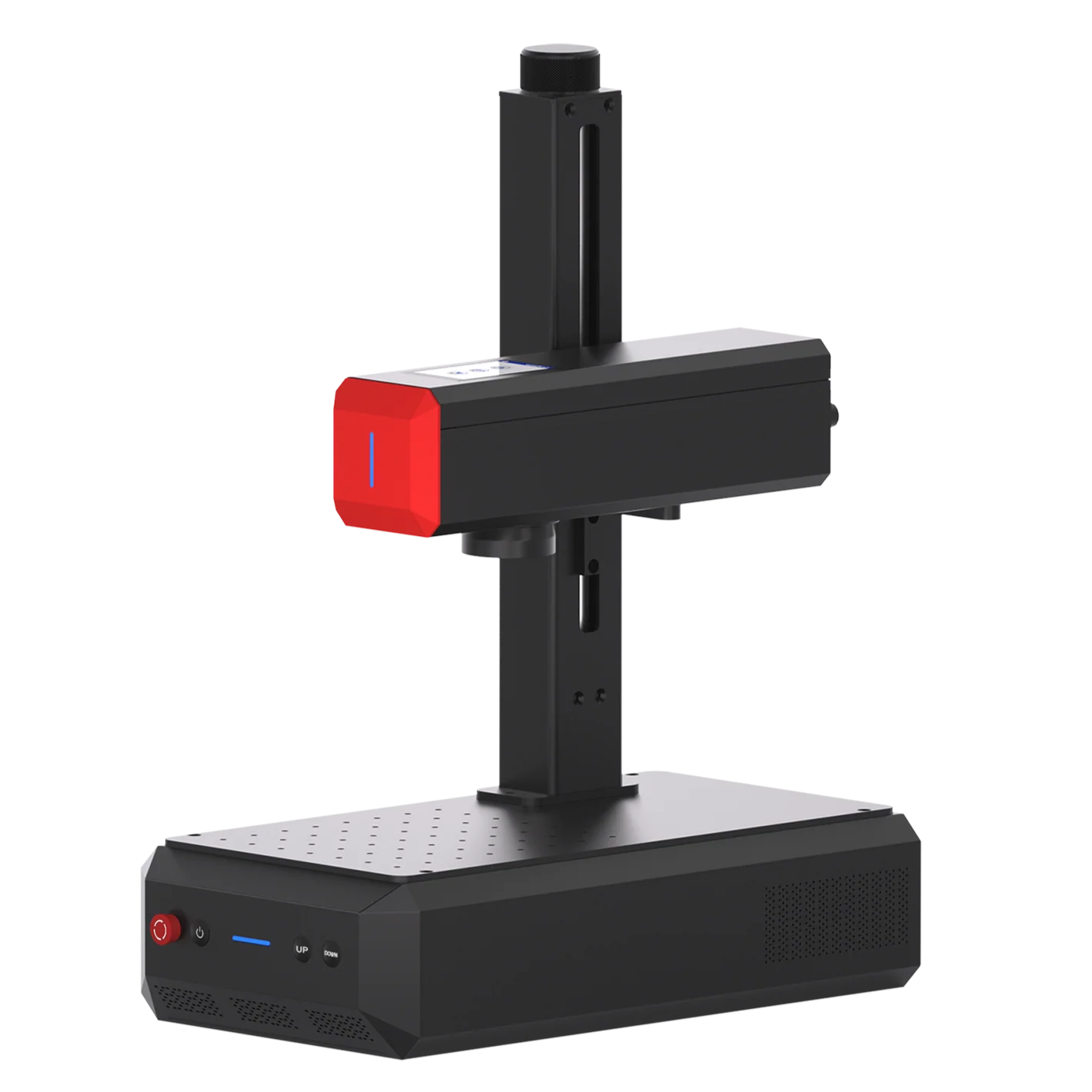
In this guide, we’ll walk you through how to use the ComMarker B6 Mopa 60W fiber laser engraver to engrave your own PCB, step by step.
How to Engrave PCB with Fiber laser engraver
Step 1. Preparing the PCB for Engraving
The first step in engraving a PCB is to properly secure the board. Use tape to firmly fix the PCB to the work surface. This is crucial because any movement during the engraving process will misalign the circuit path and holes. Ensure the PCB is securely in place before starting.
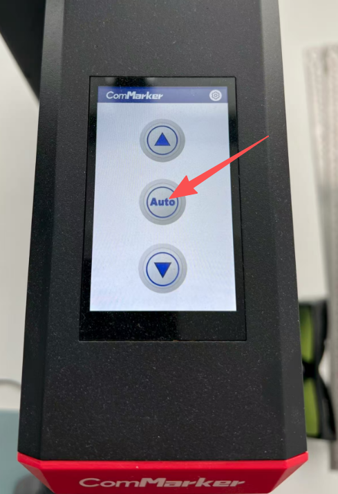
Step 2.Setting Up the Laser Engraver
Before engraving, you must set the PCB at the optimal focal distance. The ComMarker B6 Mopa 60W fiber laser comes with an automatic focus feature that simplifies this process. Simply press the auto buton on the screen, and it will adjust to the best focal distance for precise engraving.
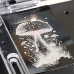
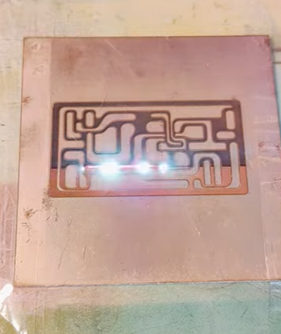
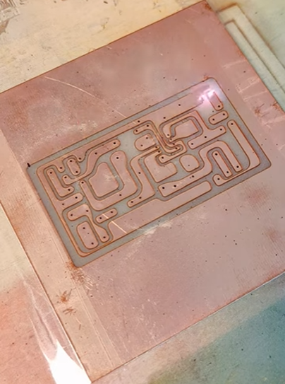
Step 3. Engraving the Circuit Design
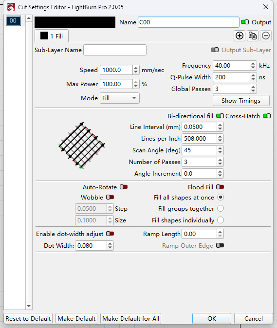
Now it’s time to start engraving the circuit design on the PCB. For this step, we’ll use higher power settings to ensure the etching is clear and precise. Here are the recommended settings for this part:
-
Speed: 1000 mm/s
-
Power: 100%
-
Frequency: 40 kHz
-
Q-pulse: 200 ns
-
Line Spacing: 0.05
-
Scan Angle: 45°
-
Number of Passes: 3
-
Check: Bi-directional fill & Cross Hatch
This will provide you with a clear, well-defined circuit pattern. If the surface feels rough after this step, a second cleaning pass may be necessary.
Step 4. Cleaning Up the Engraving
After engraving the main circuit design, the surface may appear slightly rough. To smooth it out, perform a secondary engraving with lower power settings for a cleaner finish. Here’s how you can set up the laser for this cleanup step:
-
Speed: 1500 mm/s
-
Power: 20%
-
Frequency: 100 kHz
-
Q-pulse: 200 ns
-
Line Spacing: 0.01
-
Scan Angle: 0°
-
Number of Passes: 2
-
Check: Bi-directional fill & Cross Hatch
This will provide a smooth, clean finish, removing any excess material and leaving a precise engraving.
Drilling Holes and Cutting the PCB
After engraving the circuit design, it’s time to drill the holes and cut the PCB. For drilling, switch to the line mode in your laser software. The following settings are ideal for drilling and cutting the PCB:
-
Speed: 100 mm/s
-
Power: 100%
-
Frequency: 40 kHz
-
Q-pulse: 200 ns
This will ensure that the holes are drilled with precision, and the PCB is cut to the desired shape.
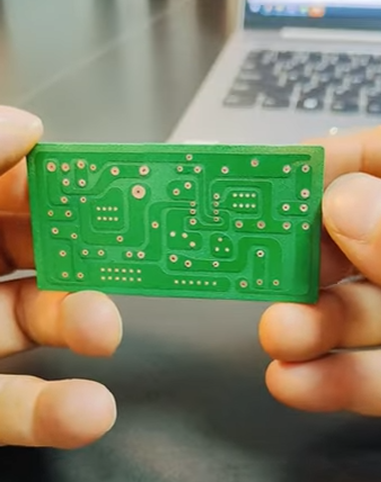
Final Touches and Insulation
Once the PCB is engraved and drilled, you can add an extra layer of insulation paint on the surface to protect it from damage. To maintain the high-quality look of the PCB, remove the insulation layer from the drilled holes using the following settings:
-
Speed: 1000 mm/s
-
Power: 50%
-
Frequency: 40 kHz
-
Q-pulse: 200 ns
After completing these steps, you will have a fully functional and professional-looking customized PCB ready for use.
FAQ
Can a 20w fiber laser engrave PCBs?
Yes. While this article focuses on 60W fiber laser engraving, a 20W fiber laser can also engrave PCBs.
For 20W fiber lasers, similar results can be achieved by lowering the speed and increasing the number of passes.
Can UV laser engrave PCBs?
Yes. UV laser engravers produce great detail with minimal damage. For example, using a 12W UV laser engraver like ComMarker Omni X and a 70mm lens, you can mark PCBs with the following settings: Passes: 2, Speed: 500 mm/s, Frequency: 50 kHz, Pulse: 5 ns, Line Distance: 0.03 mm.
Conclusion
Using the ComMarker B6 Mopa 60W fiber laser engraver for PCB engraving allows you to achieve high precision and quality results. Whether you’re engraving simple circuit designs or custom PCBs for your business, this technology offers a reliable and efficient solution. By following these steps, you can create high-quality, custom PCB engravings, and take your circuit-making skills or business to the next level.