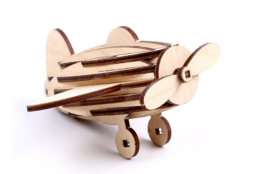
Plywood laser-cut assembly projects from puzzles and mechanical toys to storage boxes, lamps, and architectural models are among the most popular products for desktop laser engraving and cutting machines.
Most failed laser-cut assembly projects are not caused by the laser itself. They usually start with small design or file preparation mistakes that become obvious only after cutting. However, even a perfect design requires a machine with sufficient precision to reproduce small joints, tabs, and decorative details accurately.
A successful project requires both a correctly prepared file and a machine that can accurately reproduce the design.
Part 1: File Preparation Mistakes
Duplicate paths – the hidden lines that burn your project
Two identical cutting paths stacked on top of each other look fine on screen, but the laser sees two separate commands.
Running the same path twice builds up excess heat, causing darker or charred edges, wider cuts, and material damage, especially risky with plywood, cardboard, or veneer.
This often happens when copying and pasting, merging svg files, or manually aligning parts.
Fix: before exporting, select all objects, remove duplicates, merge overlapping shapes, and check each layer.Then switch to outline mode to spot hidden lines.
Open paths – your laser cuts but the part stays attached
A path may look closed but have a tiny gap (even <0.01 mm).
The software may treat it as an open path instead of a closed shape, causing incomplete cuts or parts that remain attached to the sheet.
Fix: select all cutting paths, join open nodes, and confirm every shape is truly closed.
Illustrator: object > path > join
inkscape: path > combine
Never judge a file by appearance alone. Always verify closed paths, correct layers and colours, operation types and hidden geometry
Text not converted to outlines – the font that breaks your design
Editable text relies on fonts installed on your system.
When someone else opens the file without that font, text auto-replaces—shifting letters, cutting positions, or even removing characters.
Fix: convert all text to vector outlines before exporting.
Illustrator:select text > object > expand > create outlines (ctrl+shift+o)
Then check:select > object > text objects
Production files should contain only geometry: vector paths, cutting lines, engraving areas, and separated layers.
Part 2: Structural Design Mistakes
Mixing cutting and engraving lines – your machine does the wrong job
A laser does not understand intent—it follows settings.
If engraving and cutting share the same layer, results can cut through engraving lines while cutting lines only lightly marked
Fix: separate every operation into distinct layers in the software, or import cutting and engraving design separately.
This prevents part movement and improves accuracy.
No bridges/tabs – small parts disappear during cutting
Tiny parts can become loose at mid job. Airflow, material movement, or incomplete cutting can cause small parts to shift, or be lost during cutting.
Fix: add small uncut tabs to hold parts in place.
Best practice:
• add 2–4 tabs per small part
• place on non-critical edges
• avoid precision fitting areas
After cutting, remove manually and sand smooth.
No kerf compensation – your parts never fit together
When the laser cuts, it removes material, creating a width called kerf, which varies based on laser type, material, thickness and settings
If you design a 10 mm tab and 10 mm slot: During cutting, material is removed along the path. Without kerf compensation, tabs usually become slightly smaller and slots are slightly larger than designed.
Fix: Always test your actual machine and material and offset your insert to the size of kerf.
Ignoring material thickness – flat designs fail in 3d
Design software works in 2d, but real materials have thickness and volume.
Example:
a 10 mm slot in 3 mm plywood may cause misalignment or collisions in assembly.
For complex projects, create a simple 3d mock-up first.
Part 3: Precision Limits-When Details Become Too Fine
Designing structures too thin – details break before assembly
The strength of a laser-cut assembly part depends on the amount of material left between cutting lines. This remaining material acts as the “supporting rib” of the design.
If the rib width is too narrow, the part may break during cutting, handling, or assembly. This is especially common with plywood, where heat can weaken the layered structure.
Fix: check the minimum feature size before cutting. Slightly increasing the thickness of small supporting structures can greatly improve durability.
For detailed assembly projects, always balance appearance and structural strength. A design that looks impressive on screen may not survive physical assembly.
Cutting lines too close together – heat damages fine details
Dense patterns and closely spaced cutting lines are common in decorative designs, but they can create excessive heat concentration.
When two cutting paths are too close, the surrounding material may burn excessively, causing dark edges, melted areas, or even unwanted connections between cuts.
Fix: keep enough spacing between cutting lines.
As a starting point, avoid placing critical cuts too close together. Many designers leave spacing around 1–2 times the material thickness, then adjust based on laser power, material, and desired edge quality.
Engraving too close to cutting lines – protect fine details
Engraving and cutting use different laser parameters. However, the heat generated during cutting can affect nearby engraved areas, causing discoloration or loss of fine details.
Fix: keep engraved areas at least 3mm away from cutting lines whenever possible.
If engraving and cutting must be close together, complete the engraving first, then perform cutting as the final operation. This reduces the chance of heat damage affecting detailed patterns.
How high-precision lasers expand design possibilities
While file preparation determines whether a project can be assembled correctly, laser precision determines how much detail your design can achieve.
| Project requirement | Recommended laser capability |
| Cutting thick plywood panels | High-power CO2 laser cutter or suitable high-power laser system |
| Cutting small precision parts | CO2 laser & UV laser |
| Adding fine details to assembled wooden products | UV laser engraving |
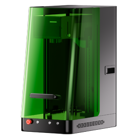
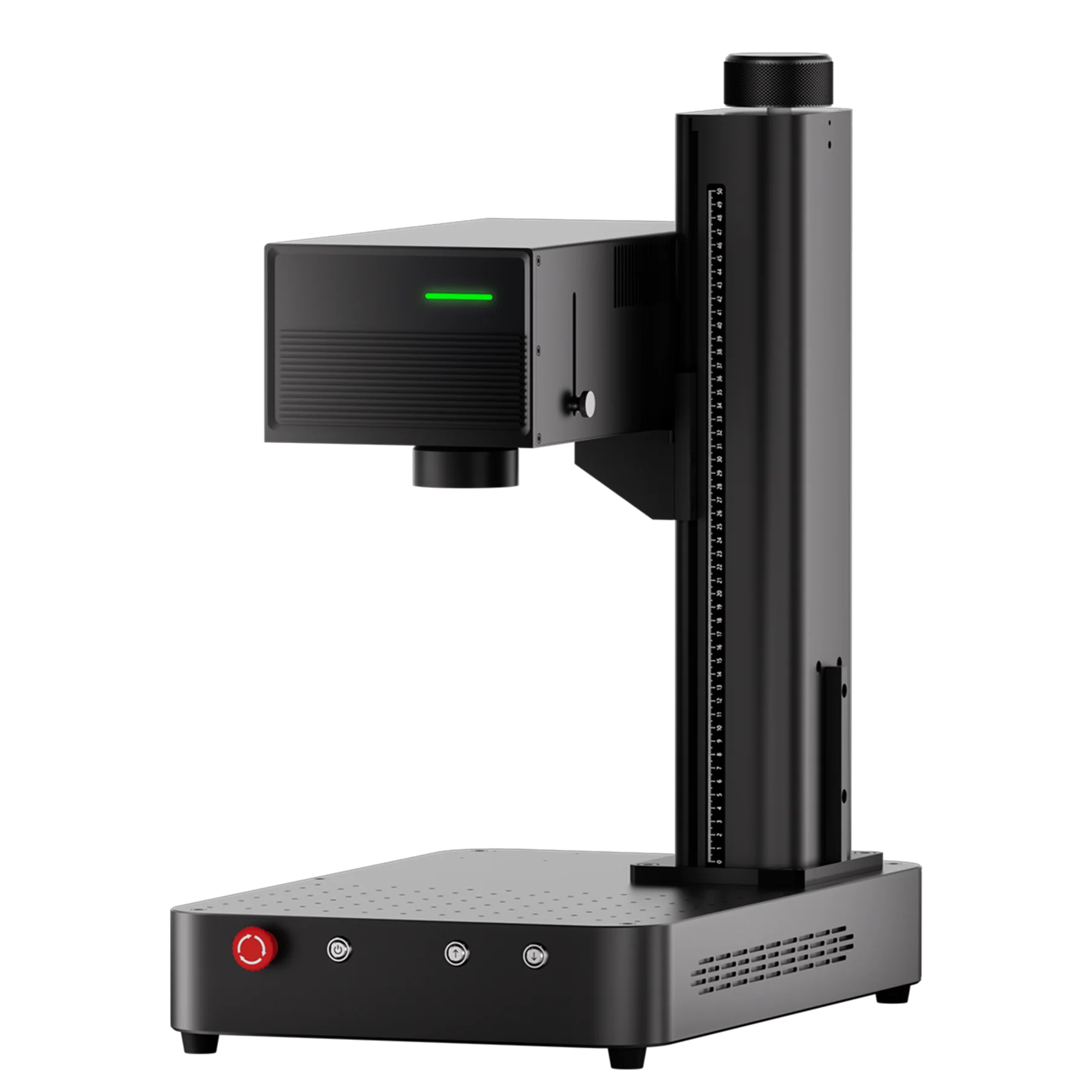
For projects where engraving details matter as much as cutting accuracy, such as decorative plywood panels, personalized models, and small detailed components, the ComMarker Omni X UV laser engraver can provide cleaner marking with less thermal impact.
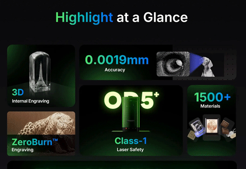
Key advantages include:
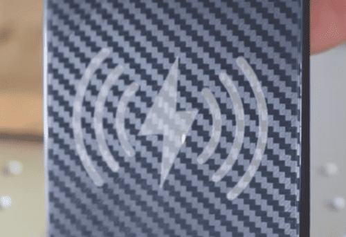
• 0.0019mm spot size for 16k HD engraving details
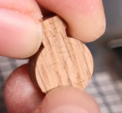
• Reduced heat impact for cleaner edges and 0.5 mm thin structures on plywood
• Better precision for small features and detailed designs with 0.3mm thin kerf
• Sharp cutting edge for premium designs
Disadvantage: Galvo laser creates slop on the edge when engraving area is far from the laser head.
 |
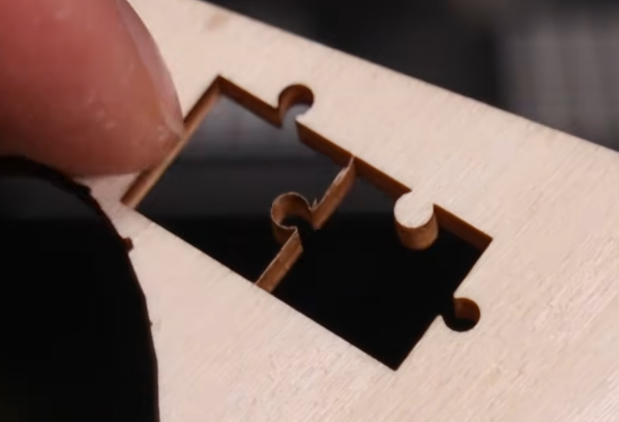 |
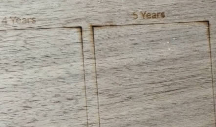
(Thin kerf & thin structures with UV laser engraver)
 |
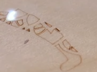 |
| diode laser cutting edge | uv laser cut edge |
Conclusion
The best laser cutting results come from combining:
• good design
• correct file preparation
• suitable laser technology
By avoiding these mistakes, you will reduce material waste, minimize rework, improve accuracy and increase production efficiency
And when your machine delivers higher precision, your design is no longer limited by the machine’s precision, allowing you to create more detailed and reliable projects.