In the manufacturing of industrial instruments—such as optical stages, metrology tools, aerospace control panels, and custom medical dials—components must balance mechanical structural complexity with permanent, micro-precise visual data. Whether it is a 360-degree rotation scale, localized part specifications, or barcodes for industrial tracking, the contrast and position of these markings cannot degrade over decades of operational wear.
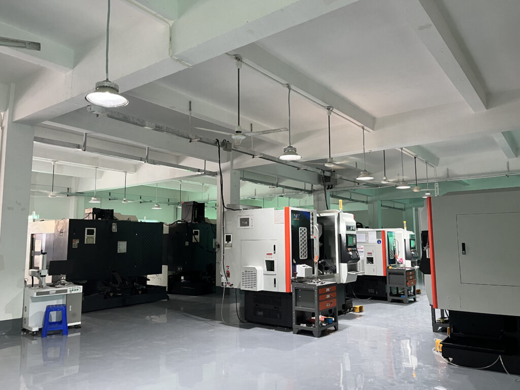
Achieving this high standard requires a two-stage sequential workflow: using high-rigidity CNC milling to establish the 3D geometry, followed by using advanced fiber or UV laser workstations to execute permanent, high-contrast engraving.
For hardware designers and manufacturing engineers, integrating these two distinct processes involves clear cross-disciplinary constraints. Here is a technical breakdown of how CNC machining and specialized laser scribing work in tandem to produce high-end precision components.
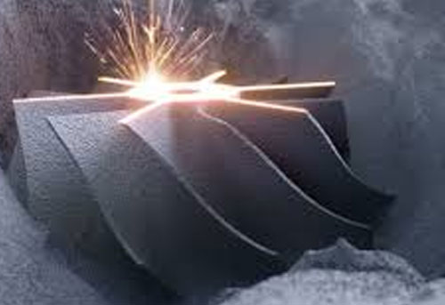
1. Preparing the Geometric Canvas: CNC Pocket Milling and Counterboring
A laser beam cuts metal through localized thermal ablation, making it highly efficient at vaporizing or annealing steel, aluminum, or brass. However, it is fundamentally a 2D or 2.5D surface process with a limited focal depth. If a calibration mark or parameter grid must survive heavy friction, abrasive environments, or frequent handling, it cannot simply sit on the outermost surface of the workpiece; it must be physically recessed.
This is where CNC machining sets the stage:
Recessed Pocket Milling: Before the metal part reaches the laser workstation, a CNC milling machine cuts a shallow, recessed pocket or counterbore into the metal block. Placing the laser-scribed serial data or calibration grid within this machined pocket shields the laser markings from physical contact, preventing surface abrasion from wearing away the graphics.
Edge Alignment and Boundary Definition: CNC machining handles the bulk material removal, leaving clean, sharp 90-degree internal steps that define the borders of the marking zone. This gives the instrument a professional, premium aesthetic while providing a physical tactile locator for assembly.
2. Eliminating Focal Errors via Micron-Level Flatness Control
A laser beam is focused through an f-theta lens to achieve a microscopic spot size, which concentrates the energy required to mark metal. This focal point has a very tight depth of field, often within fractions of a millimeter.
If the metal substrate suffers from warping, uneven thickness, or poor surface flatness, the distance between the laser lens and the metal surface will vary across the workpiece. As the laser moves across the out-of-flat part, the beam goes slightly out of focus. This causes the laser energy to scatter, resulting in uneven marking depth, faded lines, and a severe loss of contrast on critical parameters or fine scale increments.
To maximize the output of a high-speed laser, the metal stock must be precisely prepared:
Face Milling Precision: Production facilities ensure that the base of the machined pocket is perfectly flat, holding thickness tolerances within <= 0.02 mm across the entire plane.
Surface Preparation: Machining the area at high spindle speeds creates a consistent surface finish with a roughness profile of Ra 0.4 – 0.8 microns. Eliminating deep machining cutter lines prevents micro-shadowing during the laser scanning pass, allowing the laser to burn evenly and create uniform dark oxides or deep engravings.
3. Choosing the Right Laser Technology for Machined Metallics
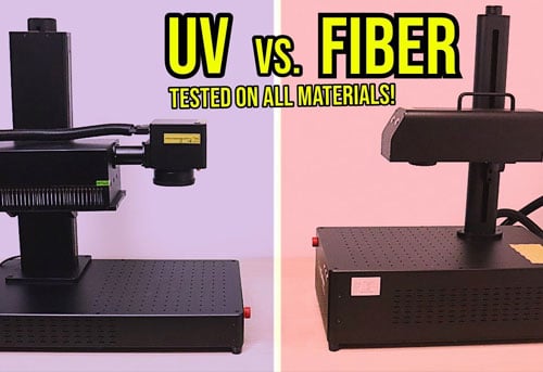
Once the flat, recessed canvas is pre-machined, the component transitions to dedicated laser setups depending on the mechanical and aesthetic requirements of the instrument. Modern engineering workflows utilize two main laser architectures to input data onto CNC substrates:
High-Speed Fiber Lasers for Deep Scribing and Calibration Scales
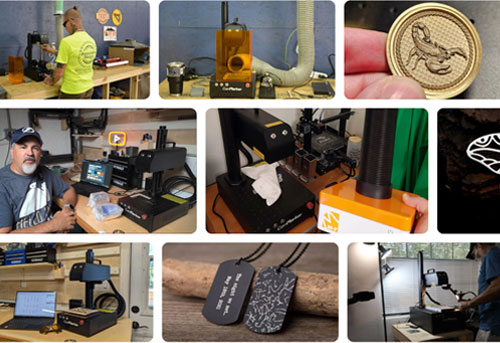
For industrial components like stainless steel dials or hard aluminum scales requiring high durability, a 1064 nm fiber laser workstation is the industry standard. Fiber lasers offer excellent absorption rates for laser engrvaing metal, allowing for deep scribing (0.1 mm to 0.3 mm deep) via multiple rapid overlapping passes. By tuning the pulse frequency and scanning speed, these systems can also execute dark, high-contrast annealing on stainless steel without digging into the metal, maintaining a perfectly smooth tactile finish while remaining highly readable.
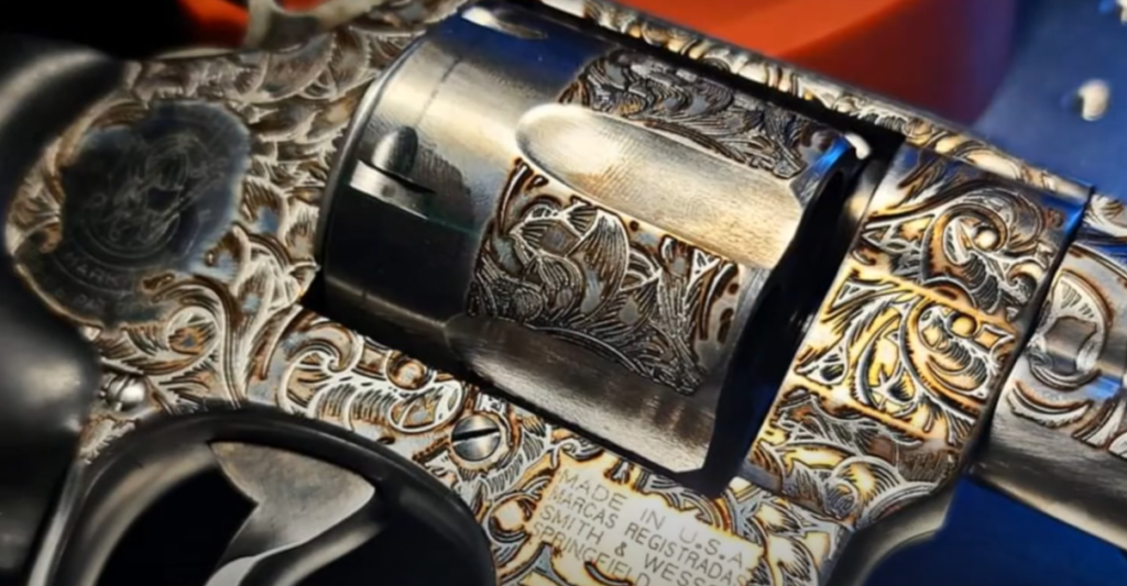
UV Lasers for Low-Damage, Ultra-Fine Markings on Delicated Components
When marking ultra-compact devices or anodized coatings where thermal stress must be completely avoided, 355 nm UV lasers are utilized. UV lasers operate via “cold processing,” breaking molecular bonds instead of relying on intense heat. This allows for microscopic graduation lines (as thin as 0.01 mm to 0.05 mm) with zero micro-cracking or thermal distortion. For instance, a UV machine can create clean, high-contrast white markings directly on dark anodized aluminum parts without penetrating the protective oxide layer underneath.

Conclusion: Streamlining the Industrial Workflow
The production of high-precision instrument components demonstrates that CNC machining and advanced laser technologies do not compete; they are completely dependent on each other. High-end product development requires an understanding of how the mechanical tolerances of the raw metal block directly dictate the visual clarity and accuracy of the final laser-scribed data.
Integrating these design requirements early in the prototyping phase with a reliable hardware manufacturing partner like DEK CNC Machining Services allows engineers to optimize the transition from raw billet milling to high-speed batch laser engraving, ensuring cost-effective production and professional-grade product quality.